|
Patch Panel Description
operational amplifiers . . . Eight high gain,
single ended, inverting amplifiers are brought out to the panel for
traditional analog computer patch cord programming. GP-6 amplifiers
feature high gain, high input and low output impedance, low temperature
drift, sufficient output current to drive general purpose program loads, 6
db/octave roll-off characteristics to assure stable and repeatable
operation under widely varying resistive/capacitive input and feedback
conditions.
Color coding: red, amplifier outputs; gray, summing
junctions.
summer integrators . . . Amplifiers 1 thru
4 have internal FET electronic switch networks that create SJ and SJ',
the two summing junction paths required for an integrator's initial
condition and operate modes. (Logic patched to the SW jacks control the
switches.) Networks of summing resistors and integrating capacitors enable
patch cords to program amplifiers as either summers (resistor feedbacks)
or summer/integrators (capacitor feedbacks.) As integrators, output
voltages equal the inverted integral of the sum of the input voltages
(plus/minus the initial condition) where the integration rate is the
reciprocal of the R*C time constant. (A combined "1" input resistor and
"B"feedback capacitor equals a nominal one second.)
When programmed as an integrator, SJ becomes the "operate" summing
junction and SJ' the "initial condition" summing junction. In the IC mode,
when SJ' conducts, the amplifier is programmed as a unity inverter with
the IC jack the input. The integrating capacitor is charged to the output
voltage so that with the IC to OP mode change, integration starts with the
output voltage. In the HD mode, the SW logic voltage is forced to the
"hold" state, the input resistor network is electronically disconnected
from the SJ summing junction and the output is held until released. GP-6
integrators employ a three state logic: ground or positive for the IC
mode; less than 5 volts for the OP mode; between minus 2 and 3 for the HD
mode.
Color coding: red, amplifier outputs; green, resistor and IC
inputs; gray, summing junctions.
summer amplifiers . . . Absence of SW
control patching latches the SW logic into the SJ conducting state. A
resistor patched as feedback programs a summer. (Amplifiers 1 thru 4 may
use the initial condition network as the resistor feedback and an
additional resistor as an input by patching jacks SJ to SJ'.) The summer
output voltage equals the inverted sum of inputs where input gains are the
ratios of the feedback to input resistors.
Resistors may also be externally connected. Comdyna offers special
module-plugs to add inputs or special non-standard resistor values.
Color coding: red, amplifier outputs; green, resistor and IC
inputs; gray, summing junctions.
inverters . . . Amplifiers 7 & 8 apply
internal input and feedback resistors (summing junctions not brought to
the panel) for use only as gain one, sign inverters.
Color coding: red, amplifier outputs; green, inputs.
coefficient potentiometers . . .
Potentiometers are used primarily for entering parameters (constants) into
a program. Pots 1 thru 6 are programmed as grounded attenuators, 7 and 8
as ungrounded voltage dividers. As attenuators, inputs (top jacks) are
multiplied by "settings," (adjustments between 0 and 1.0) and terminated
as wiper outputs (bottom jacks.) As voltage dividers, the wiper voltages
(middle jacks) are the "settings" times the differences between the top
and bottom jack voltages.
Color coding: yellow, inputs, wipers and bottoms.
multiplier/dividers . . . Multiplier networks
may be programmed for multiplication and/or division of two analog
variables. Multiplication of X and Y inputs occurs when the network is
patched to an amplifier summing junction and the feedback is a resistor.
Division of U by X occurs when the network is patched to the summing
junction, the X input is patched as the feedback, the denominator is
patched to the Y input and the numerator U to an input resistor.
Color coding: brown, inputs; gray, network summing junction.
positive/negative 10V REFERENCE . . . A
precision, positive and negative 10 volts reference provides a "unity"
needed for entering voltage constants.
Color coding: red, plus 10 volts; yellow, minus 10 volts.
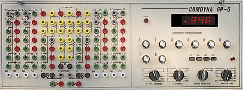
Operator Panel Descriptions
OVERLOAD INDICATOR . . . A light alarm glows
when any of the eight patch panel amplifier exceeds an overrange output,
approximately plus/minus 10 volts.
DIGITAL VOLTMETER . . . The DVM displays
coefficient potentiometer settings, the static values of amplifier outputs
and positive/negative reference.
COEFFICIENT POTENTIOMETERS . . . Eight
coefficient potentiometer knobs adjust the input/output settings.
Settings are displayed by the digital voltmeter in the POT SET mode.
Y/POT ADDRESS & X ADDRESS . . . Two
rotary switches enable amplifier outputs and potentiometer wipers to be
selected for digital voltmeter readout or output to an X-Y monitor such
as an X-Y oscilloscope or X-Y plotter.
MODE CONTROL . . . Analog computer
simulations may be conducted in either a slow time or high speed
repetitive operation output. In slow time, the operator depresses the IC,
HD and OP pushbuttons to place a simulation into the reset, hold or run
mode. Depressing the RO (repetitive operation) button speeds system
integrator time constants by 400 and repeats the reset and run modes at
rates up to 33 per second for viewing by an X-Y oscilloscope.
The MODE SELECTOR switch is positioned to POT SET for potentiometer
setting and other check-out operations. Otherwise the switch is set to
OPR.
POWER & COMPUTE TIME . . . In
addition to power on/off the COMPUTE TIME switch serves also to adjust the
compute time or integrate period in a range of 10 to 100 scaled seconds.
The time base ramp may be selected the X ADDRESS switch, TIME position, to
be the XY plotter or oscilloscope horizontal axis. |